K6JSI
UHF MASTR II Alignment Instructions
These instructions describe alignment of the RF assembly of the UHF
MASTR II receiver. The IF and Mixer alignment is not included; it rarely
needs to be performed. You will need to consult the GE MASTR II
Maintenance Manual for these instructions.
Some older receivers will not have the three trimmer capacitors (C406,
C411, and C416) on the Oscillator/Multiplier board, they will have three
inductors (L401, L402, and L403, from front to rear) with tunable slugs
instead. Follow the directions as shown, but adjust L401 instead of
C406, L402 instead of C411, and L403 instead of C411.
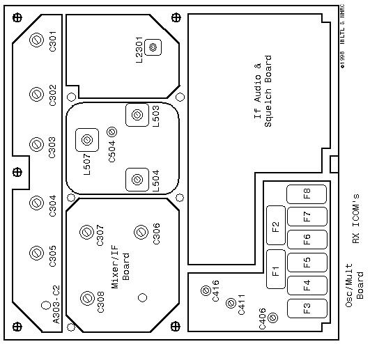
UHF MASTR II Receiver Alignment Controls Locations
|
UHF Receiver Alignment |
|||
|
Step |
Receiver |
Test Set |
Instructions |
|
1 |
3 |
C |
Peak C406. Set C411 and C416 in a similar position. Set
C306, C307, and C308 fully CCW. |
|
2 |
4 |
D |
Peak C411, then peak C416. Peak C406, C411, then C416.
Adjust C306 for some kind of meter response, either a peak
or a dip. |
|
3 |
7 |
F |
Peak C307, then C306. Peak C307 and C306 again. Dip C308,
then peak C306. Do not readjust C307 or C308. |
|
4 |
1 |
B |
Inject a signal on the receiver's frequency into the hole
adjacent to C304. Adjust the signal level for a slightly
noisy signal. Then, peak C305, C304, and A303-C2. You may
need to reduce the signal generator level one or more times
to keep the received signal slightly noisy. Alternately
reduce the generator level and adjust these three controls
to obtain the largest peak meter indication with the lowest
signal generator level. |
|
5 |
1 |
B |
Inject a signal on the receiver's frequency into the hole
adjacent to C303. Adjust the signal level for a slightly
noisy signal. Then, peak C304 and C303. Use the same method
as step 5 to obtain the largest peak meter indication with
the lowest signal generator level. |
|
6 |
1 |
B |
Inject a signal on the receiver's frequency into the hole
adjacent to C302. Peak C302 and C303 as above. |
|
7 |
1 |
B |
Inject a signal on the receiver's frequency into the antenna
jack. Peak C301, C302, C303, C304, C305, and A302-C2. If the
UHS preamplifier is present, peak T2301 as well. Keep
reducing the signal generator level to keep the received
signal slightly noisy. Peak C303 as above. |
|
8 |
1 |
B |
Leave signal injected on receiver's frequency into antenna
jack. Carefully tune C306, C307, and C308 for best quieting.
Do not adjust more than 1/4 turn. Then, carefully tune C301,
C302, C303, C304, C305, and A302-C2 for peak meter
indication and best sensitivity. A signal-to-noise analyzer
can be helpful here. Continue to tweak these 6 controls
several times until no further improvement in sensitivity
can be made. |
Mixer and IF alignment is almost never required. Do not attempt to align
the mixer or IF stages of the receiver without at least a
signal-to-noise analyzer.
The frequency of the receiver ICOM can be adjusted by turning the
trimmer capacitor on the top of the ICOM. The frequency can be measured
directly with a frequency counter connected to the junction of C416 and
L403 on the Oscillator/Multiplier board (frequency here should be
(receive frequency - 11.2) / 3) or the ICOM's frequency can be adjusted
by injecting a signal into the receiver from a known reliable source
(signal generator or service monitor) and tuning the ICOM for best
receive sensitivity.
These alignment instructions are for a UHF exciter, and conventional UHF
PA. They will not work for a "tripler-PA" radio. The conventional UHF
exciter has 8 transformers in cans and 5 variable capacitors. The
tripler-PA exciter has 10 transformers in cans and no variable
capacitors. Don't bother with the tripler -PA transmitter; they are not
suitable for repeater work.
All transmitter alignment measurements are performed with the
transmitter keyed. Do not leave the transmitter keyed for an extended
period until the alignment is complete. Make sure that a wattmeter
and dummy load are connected to the transmitter output.
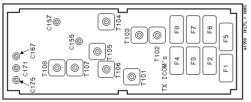
UHF MASTR II Transmitter Alignment Controls Locations
|
UHF Transmitter Alignment |
|||
|
Step |
Metering |
Test Set |
Instructions |
|
1 |
1 |
b |
Peak T101. Dip T102. Peak T103. |
|
2 |
3 |
C |
Peak T104. Dip T105. |
|
3 |
4 |
D |
Peak T106. Dip T107. |
|
4 |
7 |
F |
Peak T108. Dip C155. |
|
5 |
6 |
G |
Peak C157. Dip C167. |
|
6 |
4 |
D |
Meter is now on PA metering jack. Peak C171 and C175. |
|
7 |
1 |
B |
Meter is now on exciter metering jack. Peak T101. |
|
8 |
3 |
C |
Peak T102. Peak T103. Peak T104. |
|
9 |
4 |
D |
Peak T105. Peak T106. |
|
10 |
7 |
F |
Peak T107. Peak T108. |
|
11 |
4 |
D |
Meter is now on PA metering jack. Peak C155. Peak C157. |
|
12 |
4 |
D |
Peak C167. Peak C171. Peak C175. |
|
13 |
1 |
B |
Meter is now on exciter metering jack. Peak T101. |
|
14 |
3 |
C |
Peak T102. Peak T103. Peak T104. Repeat to find highest
peak. |
|
15 |
4 |
D |
Peak T105. Peak T106. Repeat to find highest peak. |
|
16 |
7 |
F |
Peak T107. Peak T108. Repeat to find highest peak. |
|
17 |
4 |
D |
Meter is now on PA metering jack. Peak C155. Peak C157.
Repeat to find highest peak. Peform steps 13-17 again. |
|
18 |
4 |
D |
Peak C167. Peak C171. Peak C175. Repeat to find hgihest
peak. |
|
19 |
Wattmeter |
|
Adjust power control potentiometer on Power Amplifier for
desired output power. |
Use a frequency counter or service monitor to adjust the transmitter
ICOM. The trimmer capacitor on the top of the ICOM adjusts the ICOM's
frequency, and therefore the transmitter's output frequency.
Transmitter maximum deviation is set with R104. Note that this control
adjusts the deviation level after the limiter. This control
should be adjusted to ensure that maximum deviation does not exceed 5.0
KHz. A service monitor or deviation meter is required to make this
adjustment. If you do not have the required test equipment, then don't
adjust the deviation control, it's probably fine right where it is.
When setting power level, do not exceed rated output power. If the radio
will be used as a repeater, or in any other similar high-duty-cycle
application, then the maximum output power should be derated to 1/2 to
2/3 of the specified rated output power.
Shorty, June 2001